Specification for topographic survey Property
Lawson farm
and portion of Beeler Mill property.
General
Surveyor shall do all work necessary to determine
accurately the physical conditions existing on the site. Surveyor shall prepare
a map of the given a given area in ink on plastic drafting film at scale of 1
inch to feet. Four black-line prints of the survey map shall be furnished.
Datum

Elevations shall be referenced to any convenient and
permanent bench mark with an assumed elevation of 100.0 feet.
Information
required
- Title of survey, property location, scale, north point, certification and date.
- Tract boundary lines, courses and distances. Error of traverse closure shall not exceed 1:10,000. Calculate and show acreage.
- Building setback lines, easements and right-of-way.
- Names of on-site and abutting parse owners.
- Names and locations of existing streets on or abutting the tract. Show right-of-way, type and width of surfacing and center-line of gutters.
- Position of buildings and other structures, including foundations, piers, bridges, culverts, wells and cisterns.
- Location of all site construction, including wells, fences, roads, drives, curbs, gutter, steps, walks, trails, paved areas, etc. indicating types of materials or surfacing.
- Locations, types, sizes and direction of flow of existing storm and sanitary sewers on or contiguous to the tract, giving top and invert elevations of manholes and inlet and invert elevations of other drainage structures; location, ownership, type and size of water and gas mains, manholes, valve boxes, meter boxes, hydrants and other appurtenances, locations of utility poles and telephone lines and fire-alarm boxes. For utilities not traversing the site indicate by key plan if necessary, the nearest off-site leads, giving all pertinent information on types, sizes, inverts and ownership.
- Location of water bodies, streams, springs, swamps or boggy areas and drainage ditches or s wales.
10. Outline
of wooded areas. Within areas so noted, show all trees that
have a
trunk diameter of 4 inches or greater at waist height, giving
approximate trunk diameters and common names of the trees.
11. Road
elevations. Elevations shall be taken at 50 foot intervals along
center-lines of roads, flow line of
gutter on property side and tops and
bottoms of curbs. The pertinent grades of abutting street and road
intersections shall also be shown.
12. Ground
surface elevations shall be taken and shown on a 50 foot
grid
system as well as at the top and bottom of all considerable
breaks
in grade, whether vertical as in walls or sloping as in banks.
Show
all floor elevations for buildings. Spot elevations shall also be
indicated at the finished grade of building corners, building entrance
platforms and all walk intersections. In additions to the elevations
required, the map shall show contours at 2-foot vertical intervals.
All
elevations shall be to the nearest tenth of a foot. Permissible
tolerance shall be 0.1 foot for spot elevations and one-half of the
contour interval for contours.
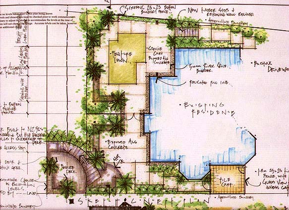
The
conceptual plan
A seed of use - a cell of function - wisely applied
to a respective site will be allowed to develop organically, in harmonious
adaptation to the natural and the planned environment.
We have by now developed a comprehensive program
defining the proposed nature of our project. We have become fully aware of all
features of the total environs. Up to this point, the planning effort has been
one of research and analysis. It has been painstaking and perhaps tedious, but
this phase is of vital importance because it is the only means by which we can
achieve full command of the data on which our design will be based. From this
point on, the planning process becomes one of integration of proposed uses,
structures and site.
Plan
concepts
If structure and landscape development are
contemplated, it is impossible to conceive one without the other for it is the
relationship of structure to site and site to structure that gives meaning to
each and to both.
This point perhaps raises the question of who on the
planning team – architect, landscape architect, engineer or other – is to do
the “conceiving”. Strangely, this problem, which might seemingly lead to warm
debate, seldom arises for an effective collaboration brings together experts in
various fields of knowledge who, in a free interchange of ideas, develop a
climate of perspective awareness and know-how. In such a climate, plan concepts
usually evolve more or less spontaneously. Since the collaboration is arranged
and administered by one of the principals (who presumably holds the
commission), it is usually this team leader who coordinates the planning in all
its aspects and gives it expressive unity. It is the work of the collaborators
to advance their assigned planning tasks and to aid in the articulation of the
main design idea in all ways possible.
Nice post about landscaping. its very good to learn.I am planning to do our courtyard lanscaping.Prefers lawn and some flowery plants with a walkway.Area is 1500sq ft.How much will a lanscapist charge ?What will be the charge for design alone ?Is it done on sq ft basis ?Pls help ...Thanks in advance.
ReplyDelete